Progressive cavity pumps are widely used in various industries due to their ability to handle viscous fluids and provide a consistent flow rate. Understanding the diagrams associated with these pumps can greatly enhance one’s ability to operate and maintain them effectively. This article will explore the key components of progressive cavity pump diagrams and their significance.
What is a Progressive Cavity Pump?
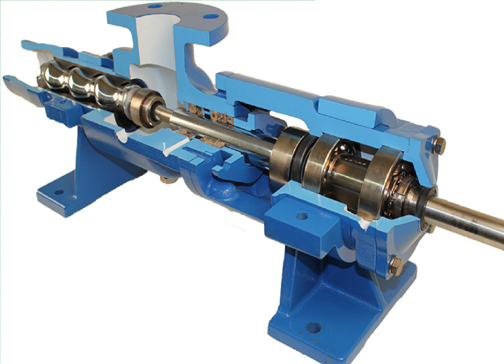
A progressive cavity pump is a type of positive displacement pump that uses a helical rotor and a stator to move fluids. The rotor, which is typically made of metal, turns inside the stator, creating cavities that transport the fluid along the pump’s length. This design allows the pump to handle a wide range of fluids, including slurries, chemicals, and viscous materials.
Key Components of the Diagram
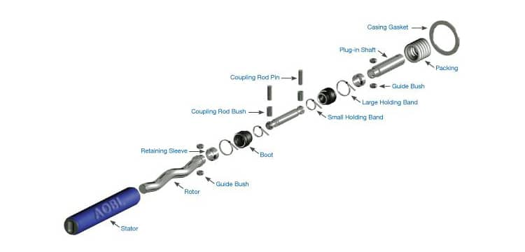
Understanding the diagram of a progressive cavity pump involves recognizing its main components. Here are the primary elements typically depicted:
- Helical Rotor: The rotating component that creates the cavities for fluid movement.
- Stator: The stationary part that encases the rotor and forms the seal that allows for the movement of fluids.
- Suction Inlet: The entry point where the fluid is drawn into the pump.
- Discharge Outlet: The exit point where the fluid is expelled from the pump.
- Drive Shaft: The component that connects the rotor to the motor, enabling rotation.
- Bearings: Support elements that reduce friction and wear on the rotating parts.
Understanding the Flow Path
A progressive cavity pump diagram typically illustrates the flow path of the fluid. It starts at the suction inlet, where the fluid enters the pump. As the rotor turns, it creates a series of expanding and contracting cavities that push the fluid toward the discharge outlet. This flow path is crucial for ensuring that the pump operates efficiently and effectively.
Benefits of Progressive Cavity Pump Diagrams
- Visualization: Diagrams provide a clear visual representation of how the pump operates, making it easier to understand the internal mechanics.
- Maintenance Guidance: By examining the diagram, operators can identify critical components that require regular maintenance or inspection.
- Troubleshooting: Understanding the flow path and component relationships can help diagnose issues when the pump malfunctions.
- Training Tool: Diagrams serve as an educational resource for new employees, enhancing their understanding of pump operations.
Conclusion
Progressive cavity pump diagrams are essential tools for anyone involved in the operation or maintenance of these pumps. By familiarizing oneself with the components and flow paths illustrated in these diagrams, operators can ensure optimal performance and longevity of the equipment. Whether used in the food, chemical, or wastewater industries, a solid understanding of these diagrams is invaluable for effective pump management.